Ducts
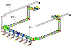
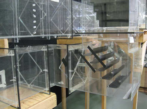
Modeling of duct flows helps in the design of flow control devices such as turning vanes and baffles to minimize pressure loss, achieve uniform flow at a particular location, and minimize particulate deposition. Field testing provides information about flow characteristics in a duct that can be used to correlate with baseline model data or provide confirmation of model results.
Minimizing Pressure Loss
Different branches of a duct system frequently have unequal flow rates due to pressure losses from the varying geometry in each branch. By properly recontouring each duct and designing turning vanes, the pressure loss is reduced and the flow is more evenly distributed. A balanced flow rate will improve the performance of heat exchangers and pollution control equipment.
Achieving Uniform Flow
In many systems, flow uniformity is required at particular locations. Proper design of turning vanes can establish uniform flow at that desired location. CFD and physical models can be used to show how non-uniform flow at inlets is controlled to be more balanced at the exits.
Minimizing Ash Deposition
Physical flow modeling can be used to assess areas of potential particulate buildup.
Field Testing
In addition to modeling, Airflow Sciences has developed a data acquisition system and custom software to perform duct and stack flow measurements in the field.