Sorbent Injection
Power plants and other industrial facilities inject a variety of sorbents in order to capture pollutants such as mercury, SO3, and other trace species. Dry sorbents (DSI), including lime, Trona, sodium bisulfide, activated carbon (ACI), and more are injected into the gas stream. Absorption of the pollutants is optimized when the sorbent distribution is uniform. Airflow Science's modeling methods have been proven by over 100 installations worldwide since 2007.
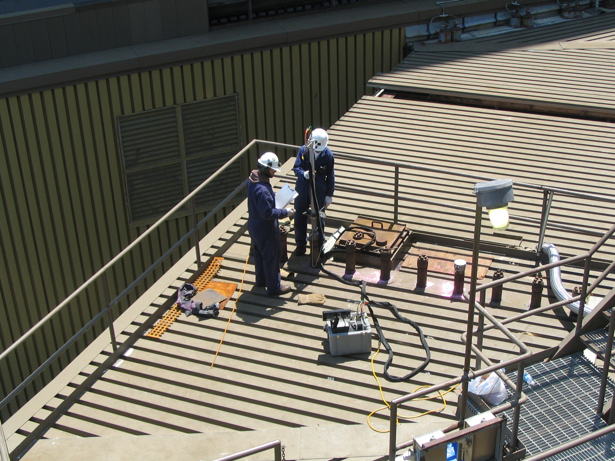 Field testing of a PJFF inlet duct velocity profile
CFD modeling of a sorbent injection system can:
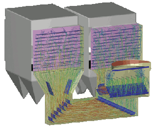 CFD model tracks the trajectory and velocity of carbon particles from the lances to the ESP
- Ensure uniform sorbent distribution
- Maximize sorbent residence times
- determine optimal sorbent feed rates
- Determine the optimum lance quantity, design, and location
- Optimize duct layout
- Ensure proper mixing within the flue gas stream for maximum absorption and capture efficiency
Field testing of the duct system can:
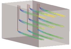 Total velocity of sorbent particles leaving lances
- Quantify flow distribution
- Determine temperature profile
- Assess ash erosion potential