Windboxes
The overall performance of a power plant depends significantly on how fuel and combustion air enter the furnace. Large fossil fuel boilers can have up to 100 individual burners that inject fuel and air. The proportion of flow through each of these plays an important role in the efficiency of the combustion process. By properly designing the combustion system, plant emissions of NOx and CO can be minimized while boiler efficiency and equipment longevity are maximized.
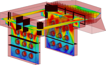
Often the engineering design process for a combustion system involves a flow model of the air and/or fuel delivery equipment. The figures show different types of models used for the design of a power plant windbox (the duct that feeds combustion air to the burners).
A fan supplies air to a scale physical model, and laboratory experiments are performed to analyze the velocity, pressure, flow rate, and other fluid dynamic properties.
CFD software calculates the air flow properties including velocity patterns, pressures, flow balance, temperatures, etc.
Using either physical or CFD modeling, a baseline analysis can help pinpoint deficiencies in the basic design. This model is then used to design flow control devices such as turning vanes, baffle plates, and measurement systems.
Windbox flows can have a significant influence on burner and combustion performance. After implementing Airflow Sciences' windbox design changes to balance secondary air, Deseret G&T's Bonanza Plant Unit 1 realized an 8% decrease in NOx, a 40% reduction in unburned carbon, and a net heat rate improvement of 0.7%.