Erosion Modeling
ASC engineers have the experience and expertise to take on unique flow challenges, including erosion of plant equipment. Fans, screens, and other intricate components of machinery can be worn away by a combination of gas velocity, particle loading, size of particulate, particle composition, and the angle of impact of the particulate.
Through flow modeling, field testing, and physical modeling, ASC can help determine the root cause of erosion and offer solutions to correct these flow issues.
Flow Modeling
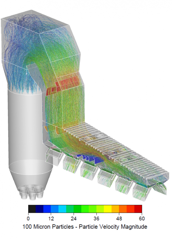
CFD modeling gives engineers more complete information to determine the cause of flow problems that lead to erosion. A computer representation of the flow behavior is created and provides details on velocity patterns, pressure drops, and temperature. Particles can be simulated and tracked to show erosion potential.
 |
||
| CFD Model with Particle Paths Defined | CFD Model of a Scrubber/Baghouse with Particle Paths Defined |
Field Testing
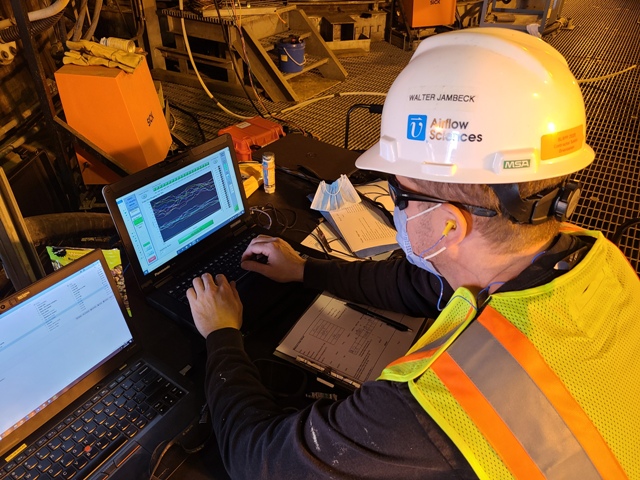
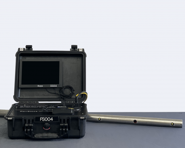
Testing at your facility gives real time information on the causes of erosion in your particular environment. Measuring the 3-D velocity profile provides the particle angle of impact. ASC engineers perform online inspections using our Flow Scope Hi-T Inspection Camera, which provides real-time video inspection of systems operating at up to 750oF.
 |
 |
|
| ASC Conducting Field Testing | Flow Scope Hi-T Inspection Camera |
In another example, our engineers may conduct isokinetic testing. By transversing a duct with a sampling nozzle we can identify areas where particulate may be concentrated, leading to accelerated erosion.
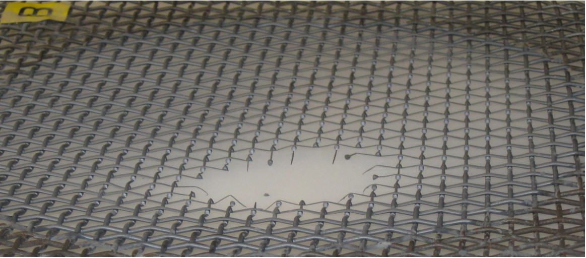
Physical Modeling
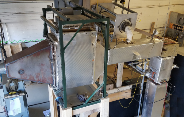
Physical modeling done in the ASC laboratory allows engineers to test within a controlled environment. The wind tunnel above has a vertical test section and includes particulate injection to evaluate erosion and pluggage of screens, filters, and other products.
Example Case – Induced Draft Fan Erosion
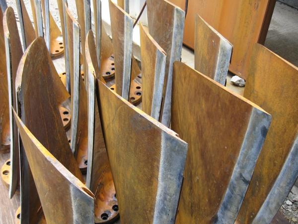
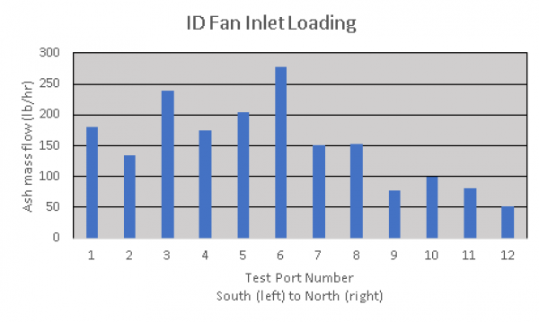
A Midwestern power plant was experiencing excessive ID fan erosion. The wear was highly uneven and our client was finding that the South ID fan was experiencing erosion at twice the rate as their North ID fan. After various trial-and-error corrections were made without success, ASC engineers were asked to conduct field testing for diagnostics and then flow modeling to redesign the system for improved performance. Note the fan tip erosion; this was confirmed by the particulate loading skewed to the South.
 |
 |
|
| Erosion on Fan Blades | ID Fan Inlet Loading Data |
After testing and modeling, ASC recommended flow control devices to distribute the particulate and reduce high velocity zones. The modifications were installed and the particulate loading issue was resolved. Plant personnel commented that the ID fan erosion became much more uniform, allowing for more consistent maintenance scheduling and no forced outages due to fan damage.