Airflow Sciences Research Leads to Better Heat Flux Boundary Conditions
By Dr. Jeffrey Franklin, P.E.
During a heat treat operation, thermal and transformational stress can cause distortion and residual stress in the component. These effects are often modeled using Finite Element Analysis (FEA) simulations. For the quenching step, the surface heat flux rates need to be specified as a boundary condition (BC) in these simulations.
Limitations of Heat Flux Approaches
Traditionally, heat flux rates used in FEA simulations have been derived from experimental data gathered from an instrumented part that passes through a heating and quench cycle. While these heat flux rates are thought to be better than a constant value, the general application of these BCs are not advisable since they are based on a specific part and a specific quenching process. Furthermore, the interpretation of the experimental data can result in more than one possible heat flux BC value, adding additional uncertainty when using this approach.
Certain commercial packages for CFD (Computational Fluid Dynamics) offer boiling models as an alternative to using experimental data, but the accuracy of these models is limited. Some models only cover a limited range of the boiling curve, while others cover the full boiling curve range but require unknown tuning parameters. Moreover, these commercially available boiling models may not be appropriate for commonly used quench oils.
ASC’s Research and Findings
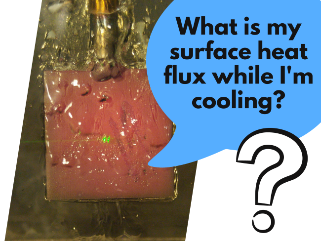
Airflow Sciences led a research effort aimed at developing a universal boiling heat transfer relationship for CFD technologies. As a product of this research, a test fixture was constructed to measure fundamental flow boiling heat fluxes. The purpose of the fixture is to hold a small surface (experimental coupon) neighbor to the quenchant at a fixed temperature while flowing a quenchant over the coupon. In this way the boiling heat flux rate can be measured, corresponding to a particular coupon temperature. The control system for the fixture regulates the heat flux to the coupon keeping the surface at a constant temperature while heat flux measurements are made. This process is repeated for a range of temperatures providing an accurate set of data detailing the heat flux vs. temperature to the coupon (the exact data required for the CFD heat transfer calculations).
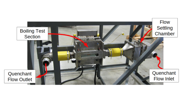
The image below shows the testing portion of the fixture removed from the full flow loop. The quenchant enters a settling chamber on the right where the flow is conditioned for entry to the center test section, after which it flows out to the left.
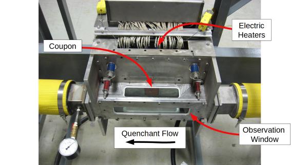
A close up view of the boiling test section (below) shows the coupon. The copper colored area inside the test section is where the detailed boiling heat flux data is collected. The observation window is used to photograph the boiling process near the heated surface.
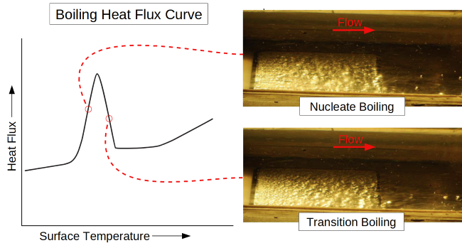
By combining a numerical flow modeling and the experimental data from the test fixture, an accurate boiling heat flux curve can be obtained. This allows a quenchant's boiling heat flux to be characterized as a function of surface temperature, surface orientation, quenchant temperature, and quenchant velocity. The image below shows a sample boiling heat flux curve alongside of the boiling images at two different points on the curve.
The video below shows a time-lapse of a single parametric experimental test. The boiling images are synchronized with the moving dot on the boiling heat flux curve.
This approach can be used to characterize the boiling heat transfer properties of any quenchant, a vast improvement from instrumented part experiments and narrow boiling models. Flow modeling with CFD, together with empirical data, provides FEA boundary conditions for more accurate heat treating simulations.
At Airflow Sciences Corporation, we have a wealth of expertise in modeling flow conditions and heat transfer for heat treat operations. Contact us to find out more about how we can help you design and improve the quenching process.
Learn more :