Ensuring Uniform Gas Injection
by Kevin Linfield, Ph.D., P.Eng., P.E.
Many engineers make a simplification by assuming a uniform mass flow distribution emanating from pipes or lances featuring multiple holes or orifices. Sometimes this can be a good assumption, depending on the relative size of the header, manifold, lances, and nozzles. Handbook calculations can be used to approximate the size requirements of each component, but a detailed CFD model of the internal piping from the manifold through the lance and out the nozzle will help ensure that the system has been designed properly for flow uniformity, temperature, and flow discharge angle.
The Design of Gas Injection Systems
Most injection systems are designed for a uniform distribution of gas, whether tempering air, ammonia, or chemical species such as natural gas for burners. Variations of up to 5% are often tolerated, but designing blind and assuming a uniform profile may result in major headaches once the system is built and operational.
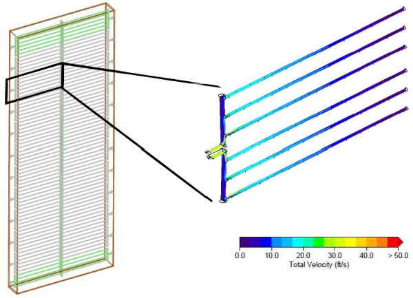
Figure 1 shows the velocity inside an Ammonia Injection Grid (AIG) for a NOx reduction catalyst. A properly designed lance should feature pressure driven flow, not velocity driven flow. Results from a detailed lance model are often used to produce boundary conditions inside a larger model of a Simple Cycle system, HRSG, or FCCU, where the velocity, temperature, and density of the flow from each nozzle is mapped into the full CFD model.
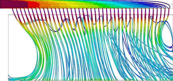
Tempering (cooling) air is often used to mix with gases that are too hot for a component (such as a catalyst) or to cool a product quickly (such as bread or meat). Figure 2 shows air flow pathlines colored by total velocity. In this case, due to the high velocity inside the supply duct, the area to the left in the figure does not receive cooling air and hence the product line cools non-uniformly.
Learn more :