How to Cool Forgings with Ambient Air (without Fans)
By Dr. Jeff Franklin, P.E.
Airflow Sciences was asked to design an enclosure to cool crank shafts immediately after they had been forged. In particular, we were asked to design the cooling enclosure to use ambient air without using fans to move the air through the enclosure.
How Buoyancy Promotes Air Movement
If you are familiar with how a hot air balloon works, you may already be thinking that buoyancy will be the mechanism used to promote air movement. If you are not familiar with the term buoyancy, it is the tendency of warmer air to rise above cooler air. The hot air balloon is a prime example of how this principle works. The air inside the balloon is heated above the temperature of the ambient air, resulting in the balloon rising. For this design, the hot forgings will provide the energy to promote air motion via buoyancy by heating the air, rather than using fans.
Case Study: Optimizing the Design of a Cooling Enclosure
This project required that a cooling enclosure be designed to house an existing conveyor line. The existing conveyor line transports recently forged crank shafts in carriers along a curvy path to a final area where plant workers handle them. The controlled cooling part of the enclosure design needed to control the cooling rate of the crank shafts as they travel along the conveyor to achieve the proper material properties. Controlling the cooling rate is the method used to achieve the proper material properties, a key objective of the design, so that a costly post forging heat treatment process could be eliminated.
We used Computational Fluid Dynamics (CFD) to evaluate the enclosure design concepts. CFD provides a method to virtually predict the 3D motion of air within the enclosure and the temperature history of the cooling crank shafts. The ability to predict this information virtually provided the ideal framework to consider potential design concepts and then further refine the designs to meet the cooling rate requirements.
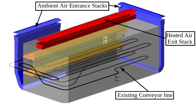
The figure above shows the final enclosure design. The geometry of the enclosure is shown as a gray box whose geometry was largely dictated by the existing conveyor line. Two ambient air entrance stacks, colored blue in the figure, allow ambient air to enter near the floor of the enclosure. One heated air exit stack, shown in red, provides an exit for the heated air to leave the cooling enclosure. The air motion mechanics is as follows:
- Air is heated by the hot crank shafts and rises to the top of the enclosure due to buoyancy.
- As warm air rises, replacement ambient air is drawn in through the ambient air entrance stacks.
- When the warm air reaches the top of the enclosure it leaves the enclosure through the heated air exit stack due to buoyancy since it is warmer than the outside ambient air.
This flow path demonstrates how the heat from the recently forged crank shafts has been used to create a type of air pump that pulls ambient air through the cooling enclosure without the need of a mechanical fan.
Project Takeaways
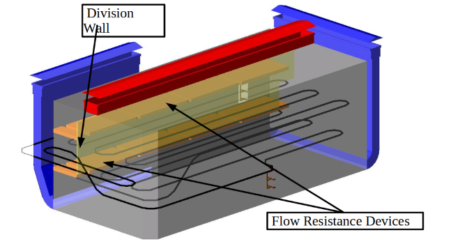
During the design phase of this project the initial enclosure design did not have any internal flow control devices present. The virtual simulation of this design predicted that the early cooling rate of the crank shafts was much too fast and the desired material properties were not achieved. Using the initial design simulation as a guide, various internal flow control devices where evaluated using CFD simulations. The final design’s flow control devices are shown in the figure above. The division wall separates the path of the conveyor line after the forge from the rest of the enclosure so that the air flowing through this region could be controlled. The flow resistance devices were then placed above and below the conveyor line to reduce the air velocity passing by the crank shafts, reducing the cooling rate in this area of the enclosure.
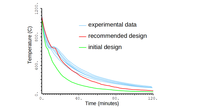
Experimental data - These curves represent thermocouple information at several locations inside a crank shaft collected during controlled cooling. The desired material properties of this crank shaft were confirmed experimentally.
Initial design - This curve shows the predicted crank shaft cooling rate for the initial design concept. Notice that the early cooling rate is much faster than any of the experimental data.
Recommended design - This curve shows the predicted crank shaft cooling rate for the recommended design.
We achieved the cooling enclosure design objectives:
- A slow cooling rate in the early stages of the crank shaft cooling to ensure proper material properties
- A rapid cooling rate in the later part of the cooling cycle to ensure the parts are cool enough for plant personnel to handle
Positive Impact for the Automotive Industry
This design project utilized CFD technologies to characterize flow-induced buoyancy in a difficult to understand situation. Buoyancy-induced flow patterns are difficult to predict via general intuition, especially when there is not a predefined flow path and energy is added to the system in a distributed fashion. CFD technologies were used to predict the flow patterns of the air passing through the enclosure along with the conjugate heat transfer aspects of the crank shafts inside the enclosure. The final design was installed by Ford Motor Co. and has been successfully used for many years. This design resulted in a reduction in manufacturing costs since the post-forging heat treatment was no longer necessary.
Do you have a design challenge that involves heating or cooling? We can help!
Learn more :
- ASC CFD Modeling Services
- Azore CFD: ASC's in-house CFD software used in this case to accurately predict buoyancy effects in flow patterns. Free 30 day trials available on their website!