Natural Gas Compressor Station Venting CFD Modeling
By Kevin Linfield, Ph.D., P.Eng., P.E.
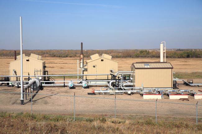
Natural gas compressor stations are a hidden component of how many people heat their houses, dry their clothes, or cook their food. Usually located in rural areas, they often consist of stacks, vents, large sections of horizontal pipes, and power sources such as gas turbines to power the compressors.
Tracking Natural Gas Plumes Using Flow Modeling
During upset conditions or gas line purges, natural gas is released to the atmosphere. Depending on the pressure and volume of the gas, these plumes may be dangerous if they intersect with ignition sources, or displace oxygen for workers to breathe.
Many gas companies use CFD flow modeling to track the gas plumes for different ambient wind conditions. Modeling can be performed "steady state", simulating a continuous emission of gas, or "transient", where the volume of gas being vented varies with time.
Case Study: External Flow of a Natural Gas Compressor Station
Airflow Sciences recently performed external steady-state flow modeling of a natural gas compressor station to determine if vented gas would be ingested into a nearby pair of simple cycle gas turbines. This flow simulation using AzoreCFD highlights the air flow patterns around the station, and tracks the concentration of natural gas as it mixes with atmospheric air.
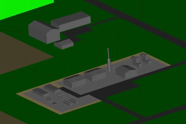
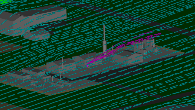
In order to accurately model the venting and dispersion process, a large portion of the surrounding area, including forests, roads, buildings, and rivers, needs to be incorporated into the CFD simulation. In some cases, the external model geometry may be over a mile in diameter and over 2000 feet high!
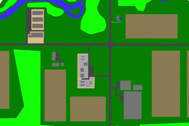
Historical wind speeds and directions are obtained, usually from local airports. Analysis of the wind rose in combination with the location of ignition sources or personnel areas determine the ambient wind conditions to model. Often, a series of simulations are undertaken to investigate "what-if" scenarios. CFD results featuring animations, streamlines, or color contours can show the path of the wind, and the effect of buildings, stacks, and other features can clearly be seen.
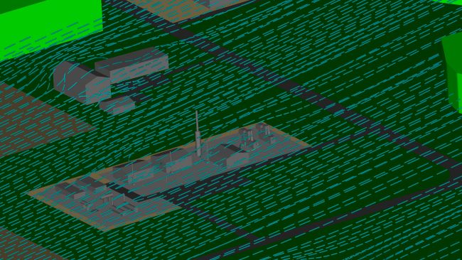
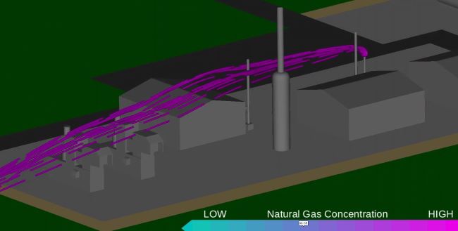
Along with the ambient wind conditions, the mass flow, temperature, pressure, and density of the natural gas play an important role in the plume height and throw. Modeling predicts the path of the natural gas, and streamlines help display this information. Here, for this particular wind condition, the natural gas plume (shown in magenta) carries over to gas turbine intakes - a potential hazard.
Risk Assessment and Next Steps
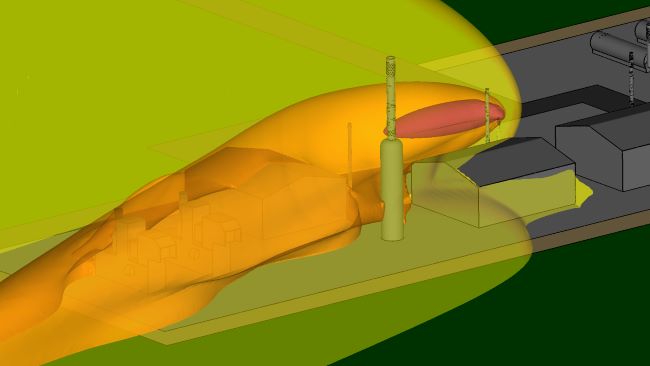
The gas is tracked and analyzed to determine if it is diluted sufficiently so no explosive or dangerous concentrations exist. AzoreCFD uses color bars to display the concentration values, and iso-surfaces allow a quick visualization of potential issues. Note the region of red and orange in this image below - a potentially dangerous situation exists under this scenario. ASC would work with our client to offer solutions to mitigate the risk, which may include relocation of stack vents, increasing the height and/or diameter of the vents, or even stack geometry additions such as caps or diffusers.
Learn more :