Safety First: Converting Boilers from Coal to Natural Gas
By Kelly Hile
EPA regulations such as the Good Neighbor Plan have challenged many U.S. power generators to reduce emissions drastically. Some coal-fired power plants have responded by converting boiler fuel from coal to natural gas. Natural gas conversions have allowed power generators to capitalize on the remaining lifespan of existing facilities and meet power demand, while at the same time lowering emissions.
Natural Gas Conversion Case Study
Converting to natural gas is not without challenges. When a coal-fired boiler is converted, there are significant risks a plant manager must consider, especially since coal-based plants do not have built-in safety measures for gas leaks. That’s why one U.S. power facility reached out to the engineers at Airflow Sciences to prove out the room design for a boiler conversion. Airflow Sciences was able to provide a multi-faceted approach to mitigate risks and prioritize safety, including flow testing onsite at the plant and computer simulation of worst-case scenario leak events, all for precise risk planning.
The plant had five 50MW boilers slated for natural gas conversion, with a room arrangement as shown below. The main objective of the design project was to ensure potential gas leaks would be detected and dissipated quickly, to avoid the accumulation of natural gas in the boiler room. Natural gas, composed mostly of methane, is lighter than air and will rise naturally in the event of a leak. Leaks are a serious hazard. As a highly flammable gas, any ignition source can cause methane to combust in the presence of air at concentrations greater than 2.8% by mass. This concentration level is called the Lower Explosive Limit (LEL).
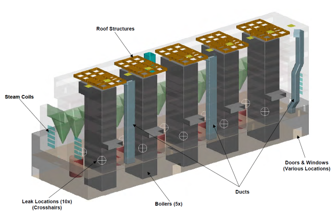
The boiler room had 50MW coal-fire boilers to be converted to natural gas
The engineering team started by assessing the ventilation in the boiler room to determine how effective the existing infrastructure might be at dissipating a methane leak. This included a site visit for measuring flow through existing fans and roof vents and assessing the rate of boiler inleakage. The existing ventilation capacity was then used to conduct a number of simulations to identify which leak scenarios presented the highest risk. The image below shows gas accumulation nearly 5 minutes into a gas leak, at a ventilation rate concurrent with normal plant operations.
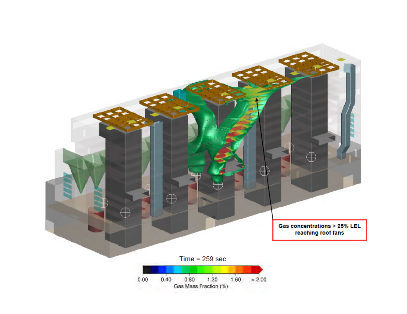
Gas accumulation above 25% of the LEL, 259 seconds after a dual-leak from the center boiler
CFD Model of a Coal-Fired Power Plant’s Boiler Room
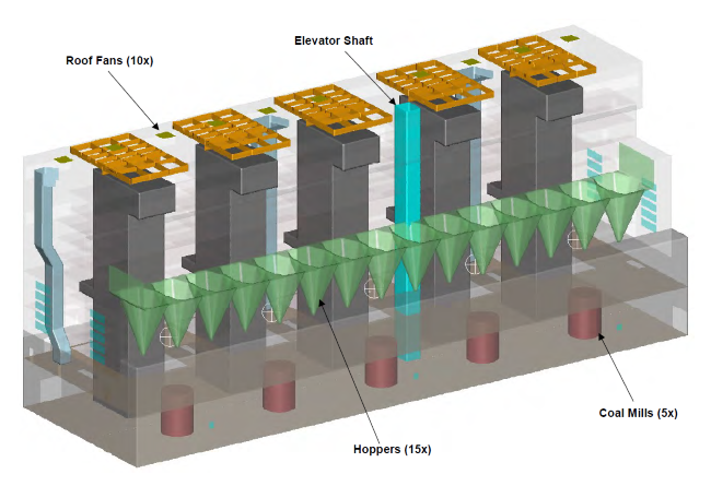
Computational Fluid Dynamics (CFD) modeling allows for cost-effective evaluation of multiple design scenarios. In this boiler room model, the team considered worst-case scenarios such as simultaneous leaks and varied sources, up to ten leaks from all five units. This enabled the ideal placement of methane sensors in the plant. The computer simulations also explored the effects of increasing fan speed and opening doors, along with room modifications such as additional roof vents or adjustable dampers. Once such a model has been developed, it can be used for virtually endless scenario testing, making subtle changes to equipment size, placement, and operating conditions.
The whole investigation aided in the development of a robust plan for responding to leaks in real time, starting from the sensor trigger point. That means that as soon as a leak is detected, the ventilation system would engage at full capacity to keep gas concentrations below the 2.8% LEL. The animation below demonstrates one such response plan, where two leaks occur at time zero (t = 0 sec) on the central boiler. The sensor is triggered at t = 30 sec, and the ventilation system is fully engaged by t = 260 sec, at which point the natural gas is dissipated to below explosive limits, allowing for containment action. In this scenario, full ventilation meant the fans were operating at full speed with doors fully open, which significantly reduced the gas concentration. The green iso-surface indicates a concentration of one fourth of the LEL.
Each of the steps in a leak response plan has a lag time. The sequence begins with the methane detector, which initiates process controls such as ramping up ventilation and turning off supply lines so that leaks are contained. There will be short time delays with each of these steps. Real-time computer simulations of the entire sequence help the design team to reduce risk by developing robust process controls and knowing exactly how much time it will take to achieve safe conditions in the boiler room.
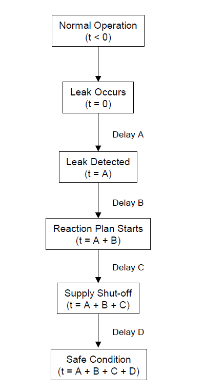
Gas leak sequence
Custom Solutions from Airflow Sciences
A specialized engineering team is an invaluable resource for handling uncertainties in the design process, especially when capital investments have the potential to impact safety. Flow simulations provide meaningful insight to help site owners protect the safety of their operators and the surrounding plant area, in addition to preserving valuable assets.
Airflow Sciences has a history of tackling tough ventilation problems with engineering excellence. Our work spans large industrial buildings, data centers, grow rooms, clean rooms, and more. The Airflow laboratory is fully equipped for fan testing or airflow testing through HVAC components or scale models of equipment. We also offer field services, with a team of engineers who perform onsite airflow testing, heat mapping, and overall system analysis. Get in touch with one of our engineers to discuss your flow-related problem and find out how we can help.