Flow Modeling as a Tool for Waste Heat Recovery Unit Performance Optimization
by Matthew Gentry, P.E.
What is a Waste Heat Recovery Unit?
A Waste Heat Recovery Unit (WHRU) is a type of heat exchanger which recovers waste heat from hot flue gases and integrates heat in to the balance of plant operations. Often sited at refineries and other industrial facilities, the WHRU can generate steam/superheating steam as well as heat thermal fluids, natural gas, various hydrocarbon fluids, and Regen Gas.
Case Study: Optimizing a WHRU through CFD and Physical Flow Modeling
For a particular WHRU being constructed at a Liquified Natural Gas (LNG) plant in the western United States, Airflow Sciences performed computational fluid dynamics (CFD) and scale physical model flow studies in order to optimize flow control devices within the WHRU system. The primary goal of the project was a uniform gas velocity distribution upstream of the heat exchanger tube banks for improved heat transfer, with a secondary goal of minimizing pressure loss.
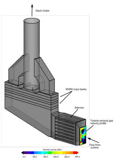
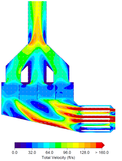
Flue gases from a Gas Turbine (GT) are used to heat a thermal fluid (hot oil) and, in turn, this thermal fluid will provide heat (approx. 200 MMBtu/hr) to various other units and equipment in the LNG plant. The flue gas velocity profile at the exhaust of the GT was highly stratified (Figure 1). Baseline CFD modeling confirmed that the resulting velocity pattern approaching the tube banks was both non-uniform and had significant angularity (Figure 2).
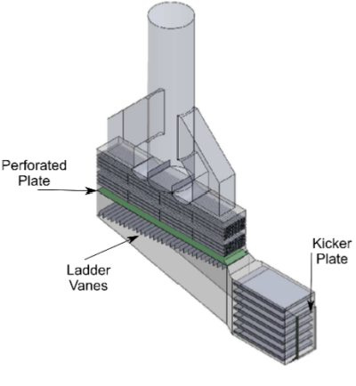
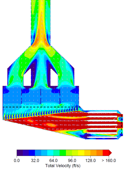
The CFD modeling design effort included an iterative approach to develop an arrangement of flow control devices (Figure 3) that achieved both uniform and aligned flow entering the tube bank region (Figure 4).
The goal of the flow modeling project was to optimize the following requirements:
- Uniform flue gas velocity distribution upstream of the first tube bank (Target: 15% RMS)
- Optimize system pressure loss
Both the CFD model and the physical model results confirmed that the above requirements were met with the final design geometry. The WHRU was constructed with these design elements. Feedback from the operating plant indicates WHRU is operating within design parameters.
Learn more :